
The wake-up call came on a Tuesday evening. I had installed a cheap IP camera in a friend's living room — one of those bargain cameras with an app you'd rather not question. Two weeks later, scrolling through the logs of his router, I saw it: the camera was talking to servers in China at 3 a.m. It had access to his entire home network — his NAS, his printer, his work PC. Not because anyone was malicious, but because everything on his side hung in one single flat network. What really got me: my own network looked exactly the same. That's exactly what VLANs are for.
VLAN segmentation sounds like enterprise switches for four-figure sums and a CCNA course. In reality, a managed switch for 35 euros, a router that speaks VLANs, and one evening are enough. This article shows the complete plan: the VLAN table with subnets, the 802.1Q trunk, the first firewall rules, and the pitfalls that nearly sank me.
Why segment at all?
A flat network is a party where every guest can enter every room. A compromised IoT device — camera, bridge, smart plug — then has the same access as your desktop. The attack path is called lateral movement: first the camera, then the NAS, then your backups. The numbers are sobering: cheap IoT devices regularly have open Telnet ports, known default passwords, or no updates at all. It's not a question of "if" but "when" one of these devices gets compromised.
Segmentation turns the all-access party guest into a guest with a single room: the camera may reach the internet (for the vendor's cloud service) but not your NAS. The guest laptop gets internet but no view of your home network. And your desktop may reach the servers, but not the other way around. That's the whole trick — and it costs less than 50 euros.
The hardware: what you really need
My homelab network setup consists of two devices that together cost under 100 euros:
- Managed switch (about 35–40 euros): The TP-Link TL-SG108E (8 ports) or TL-SG105E (5 ports) support 802.1Q VLANs and cost around 35 euros. You can also find them used for half that. For segmentation, a Layer-2 switch is entirely sufficient — the router does the routing.
- Router with VLAN support: The Fritzbox only supports VLANs to a limited degree (and often with hackery). Much better: an OpenWrt-capable router (e.g., a used TP-Link Archer C7 for 30 euros or an x86 mini-PC with pfSense). I run OpenWrt on a small x86 box with 4 ports — that makes VLANs and firewall rules clean to configure.
If you don't want to buy a second router, you can implement segmentation with a Fritzbox plus managed switch — but the switch won't do the inter-VLAN firewall, and you need a router that understands tagged frames. My recommendation: an OpenWrt router as the heart of it. That gives you VLANs, firewall, and DNS in one device you understand.
The VLAN plan: five networks, five subnets
The art isn't in the technology, it's in the plan. Before configuring a single port, I put the VLANs on paper — and worked out the subnets with the bitcalc Subnet Calculator. Each VLAN gets its own subnet from the 10-block, so nothing can ever overlap (the lesson from the VPN article). The mapping:
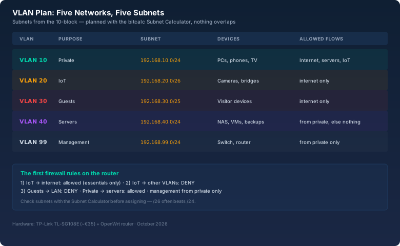
Two details from the table deserve attention:
The management VLAN (99) is the secret star. Switch and router are only reachable from the private VLAN. If an attacker breaks into another VLAN, they can't reconfigure the network infrastructure. That's one line of firewall rule — and the difference between "camera compromised" and "whole network compromised".
The subnet sizes match the device counts. For 30 devices, a /24 with 254 hosts is wasted space. I gave the IoT VLAN a /26 (62 hosts) and the guest VLAN a /25 (126 hosts) — leaving room in the 10-block for more networks. The Subnet Calculator shows host counts and usable ranges in seconds; doing that math in your head guarantees an eventual mistake.
802.1Q: tags, trunks, and the two port types
A VLAN is essentially a tag in the Ethernet frame: 12 bits in the VLAN header extension (802.1Q) telling the switch which broadcast domain the frame belongs to. IDs go from 1 to 4094. And there are exactly two port types you need to know:
- Access port: Belongs to exactly one VLAN, sends frames untagged (without a VLAN header). End devices hang here: camera, PC, NAS. The switch adds the tag internally (PVID).
- Trunk port: Carries multiple VLANs, sends frames tagged. The connection between switch and router hangs here — and it's the only place where you need tagged frames at all.
The most important rule nobody told me at the start: Tagged frames belong only on trunks. If you plug a device expecting tagged frames into an access port (or vice versa), you get exactly the "it just doesn't work" puzzles that cost nights. On the TP-Link, the config field is called "802.1Q VLAN" with a Tagged/Untagged selection per port — and the PVID sits separately. Yes, that's confusing, and yes, I got it backwards the first time.
The topology: router, switch, trunk, four worlds
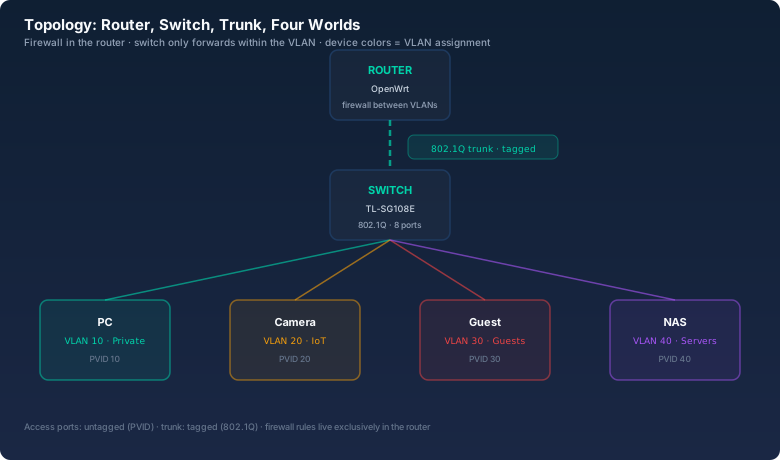
That's what the finished setup looks like. The router has one VLAN interface per VLAN (in OpenWrt: eth0.10, eth0.20, …) and handles routing between the networks. The switch only forwards frames to the right port. The firewall rules live entirely in the router — the switch is dumb in the sense that it doesn't decide who may go where, only who is in the same VLAN.
The first three firewall rules
The firewall configuration is the moment where segmentation really takes effect. In OpenWrt (or pfSense), rules are defined per interface zone. The first three rules I started with:
- IoT → internet: allowed, but only the essentials. The camera needs access to the vendor's cloud, but not to arbitrary destinations. If you like, create a rule per device — for a start, "internet allowed, everything else deny" is enough.
- IoT → all other VLANs: DENY. The core rule. The camera may reach neither the NAS nor your desktop nor management. That kills the lateral-movement path from the intro story.
- Guests → LAN: DENY, guests → internet: allowed. Visitors get network access, but no view of your home network. One exception: if you want to offer guests the printer, open port 9100 to the printer specifically — not the whole VLAN.
Plus two rules that make life pleasant:
- Private → servers: allowed. Your desktop may reach the NAS and the VMs. The reverse (servers → private) stays closed — a compromised service can't spread into your work network.
- Private → IoT: allowed. For controlling devices via the app. That's a deliberate risk you can take — or you block that too and control IoT devices only through their cloud.
The pitfalls that nearly sank it
The theory takes an hour to explain; practice cost me four evenings. The three most common pitfalls:
mDNS and the invisible printer. AirPlay, Chromecast, and some printers find each other via multicast DNS (mDNS) — and multicast stays inside the VLAN by default. After segmentation, my TV in the private VLAN suddenly couldn't find the printer in the media VLAN anymore. The fix is an mDNS reflector (in OpenWrt: mdns-repeater or reflector) that mirrors mDNS packets between selected VLANs. Without that one line of config, I would have rolled back the whole segmentation — the TV was more important than security, I thought back then.
DHCP across VLAN boundaries. The DHCP server sits in the router, the clients in the VLANs. For that to work, each VLAN interface needs its own DHCP range (in OpenWrt: dnsmasq per subnet). If you forget to assign a range to the guest VLAN, guests get no IP — and visitors without internet are bad advertising.
IoT devices with hardcoded networks. Some cheap devices have their target IP or even a default gateway hardcoded — usually 192.168.1.1 or 192.168.0.1. If your VLAN subnet differs, the device won't work. The pragmatic fix: give those devices their own subnet that matches their firmware (or return them — for some cameras, that's the better option).
What the migration achieved
Here's what became of that camera: it now sits in its own IoT VLAN at my friend's place — same plan — with internet access and nothing else. The logs there still show nightly connections to servers abroad, but they end at his firewall. I rebuilt my own network along the same lines: the NAS is only reachable from the private VLAN, the backups are untouchable for anything living in the IoT network, and guests get internet without seeing a single device of mine.
The biggest side effect for me was peace of mind: I no longer have to trust each cheap device individually. Segmentation is the difference between "the camera talks to China" and "the camera talks to China, and it doesn't matter because it can't reach anything".
Bottom line
VLAN segmentation in the homelab is no longer an enterprise topic. A managed switch for 35 euros, an OpenWrt router, and a clear plan are enough to separate IoT, guests, private, and servers cleanly. The plan is half the work: work out subnets with the bitcalc Subnet Calculator, put the VLAN table on paper, then configure. The firewall rules are three lines at the start — and they're the ones that let you sleep at night when another bargain camera talks to a server overseas.